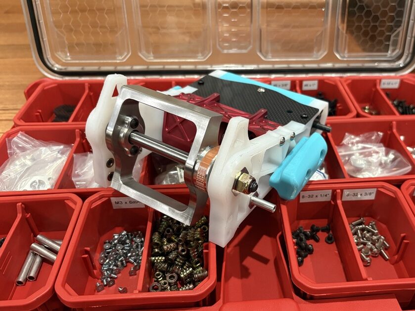
Prior to the NHRL world championship, I knew that I was not fully satisfied with the state of Pinevictus. Notably, I started my big boy job and began how hard it was to find time to make robots when all of the responsibilities of adult life existed. I also competed in 2 beetleweight events over the summer, both hosted by Team Honey Cracked in Southern MD. Both of these events ended with a my battery outside of the robot chassis, with one of such instances ejecting a battery and a lot of smoke along with it. Clearly changes must be made, with not a lot of time to do so.
I began the Pinevictus v8 CAD in October, 8 weeks to go until the NHRL world championship. Luckily, there also was a local event in Pennsylvania 2 weeks before then, and I signed up to test out the new design, with time to spare for last minute revisions. I’ve found that having deadlines means that the robot needs to be optimized for getting in the box. And I always manage to make that happen somehow.
The redesign can be summed up into 3 main points.
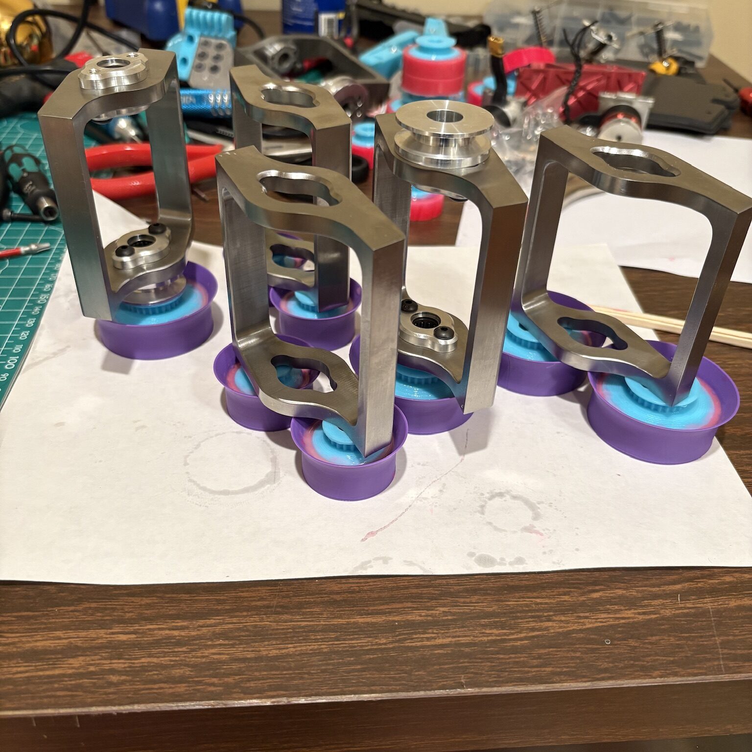
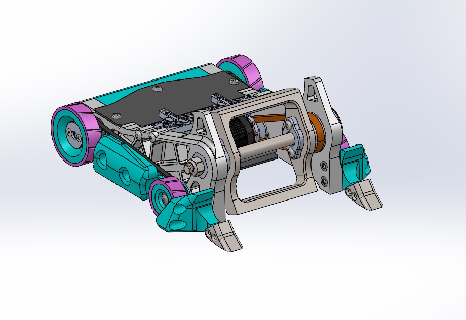
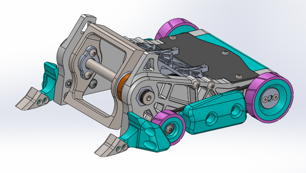
The most pressing issue was that the battery was able to eject in large IMPAKTs (rip). The packaging of Pinevictus is fairly different than the common 4WD beater bar archetype. Most people choose to design both wheel sets for indirect drive, where the drive motor and gearbox are belted to the front and back wheel. Notably Lynx and the Peter Bar Kit do this. The goal here is to protect the gearboxes from getting hit and damaged, so some extra weight is allocated for the drive system. I decided that if I am going to win, I won’t be getting hit in the back. And it’s pretty easy too, all I have to do is drive better than the opponent. So that is why recent Pinevictus’ have direct driven rear wheels. What this means however, is that the battery sits between the drive motors and the weapon. So the cross frame is what holds it together. Previously my cross frame was just a 3d printed piece. Some poor choices on my part meant that this part could flex into the path of the weapon, thus allowing the battery to enter the weapon path as well (not what you want). So thus the billet motor mount. This component serves as a motor mount and heatsink, as well as a real cross frame that ties my UHMW frame rails together. It also looks super cool, which is always the most important part of engineering. Unfortunately slapping a bunch of aluminum into the robot where it used to be flimsy 3d print comes at a cost: weight.
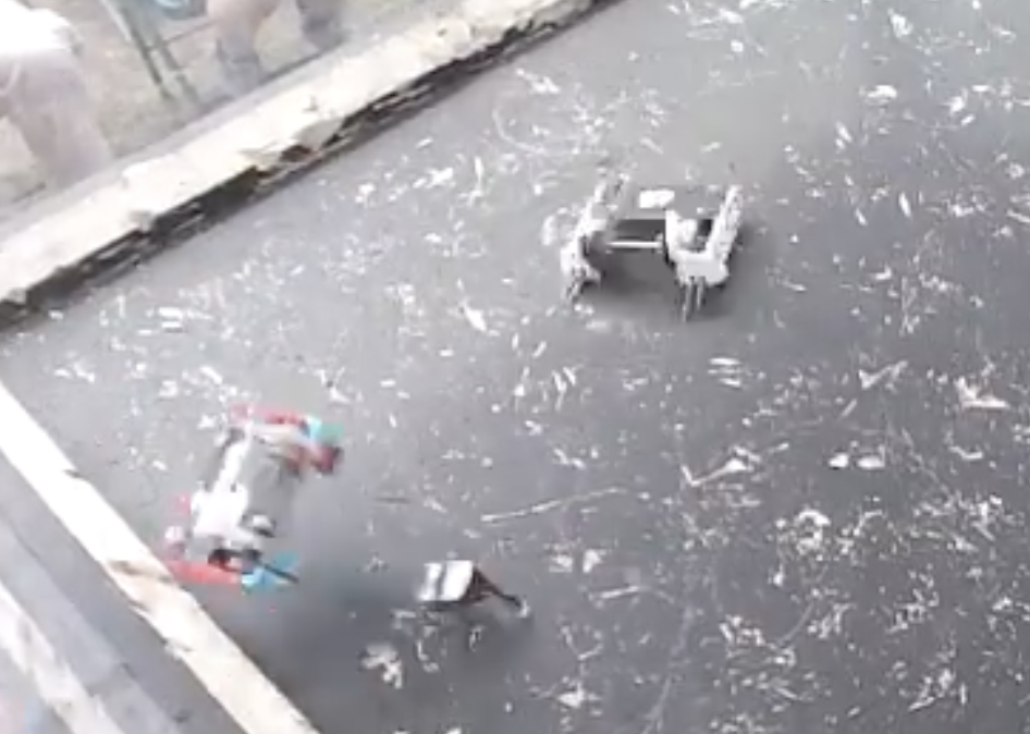
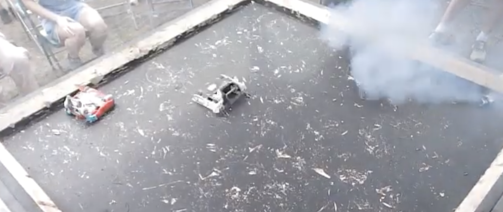
To make weight for the billet shenanigans, I went a step further. If I was going to win, I wouldn’t be getting hit in the back. I also decided I just wouldn’t get hit on the side. So I removed the wheel guards, and replaced it with a much smaller belt guard. The belt guard would offer some small amount of protection for the drive belts, and more importantly look pretty cool. We’ll see how this decision works out…
I also decided to make the beater bar a bit smaller for this event, and redo the weapon stackup. I felt that Pinevictus v7 was a bit too crazy on the gyro, so I brought in the diameter a bit to reduce the MOI. I changed the interface between the aluminum bearing supports and steel beater bar to transfer torque through keying geometry rather than screws in shear. I also now have the bearings being fully inset in aluminum to provide some slim amount of shock mounting to the bearings. Turns out it is basically the same interface as many other beater bots…
With those changes implemented to a brand-new CAD assembly, it was time to make drawings and send out files for machining. The plan was to build 4 copies with spares for 2 more. Hopefully that would prove to be enough.
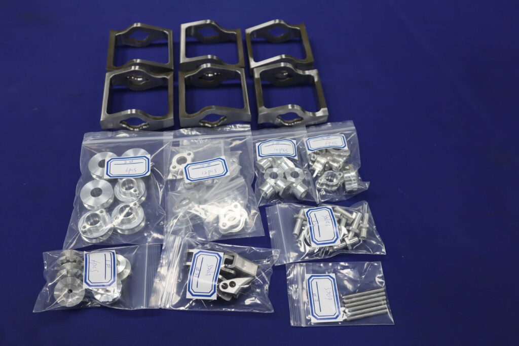
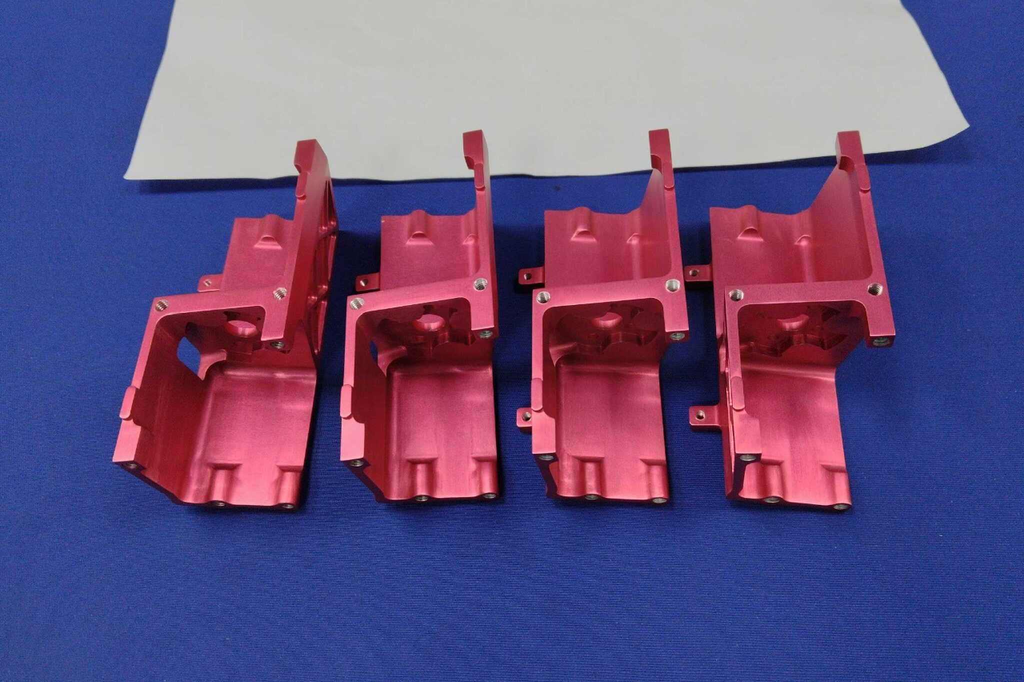
Part pictures were shared from LTCentury, and they looked fantastic as usual. Now it would be time to see if they could be used for something cool…